Parkonator
In Part 1 of the blog series I described how you can use an Arduino to capture and decode parking sensor data from cheapo parking sensors found all over Amazon. In this part I will talk about how to send this data over from one Arduino to another using I2C protocol and why you even need to worry about that.
Video Experimenter Shield
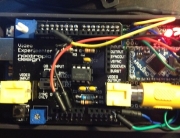
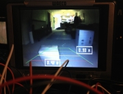
First, a word about the Nootropic Video Experimenter shield. This shield is pretty sweet, it’s cheap, it uses the TVOut library and it works pretty much as advertised. The shipping is quick too! We’ll use this shield to overlay the parking sensor information over the composite video signal coming off the read view camera (this will be described in part 3).

There is one drawback to this shield, and that drawback has to do with the fact that it requires you to use a timer and hardware interrupts in order to sync the video signal. I don’t claim to know how all that works. but you need to be aware that interrupts routines take more time to execute than you have when monitoring the ups and downs on the wire, measured in microseconds. In other words, interrupts make it impossible to read the parking sensor data on a regular Arduino (you might still be able to pull it off with the Mega, but if I recall correctly the VE shield might not work with that out of the box). This by no means is a drawback of the VE shield. It’s just something you have to deal with when you’re trying to do more with less.
So, now the question is, how do we get the data out of the first Arduino and into the second one (which will drive the video overlay)? One might think that you should use the Serial or SoftSerial library to accomplish this, but you would be mistaken. This is the original path I took and I quickly realized that the VE shield’s use of interrupts makes it impossible to use regular Serial libraries. You will find loose references about using something called PollSerial, but I was never able to get it to work correctly.. Enter I2C!
I2C Protocol
The I2C protocol is awesome, in that it doesn’t get messed up by interrupts, requires only a few wires, uses two available analog ports and allows you to hook up to 256 Arduinos together! To make things even easier, a kind gentleman who goes by the name Bill Porter has created a library called EasyTransfer that abstracts away a lot of the communication junk that you probably don’t want to deal with. We will use this library to establish communication between the two Arduinos.
Wiring For Communication
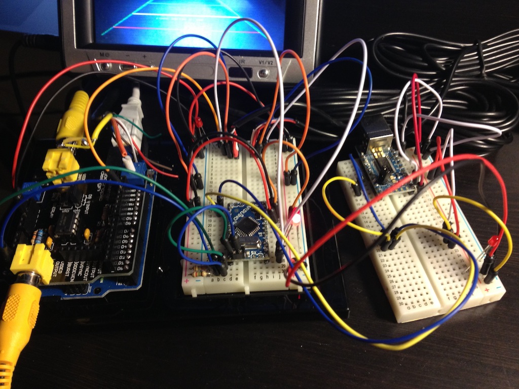
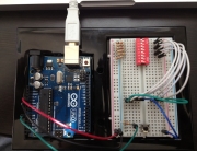
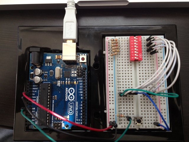
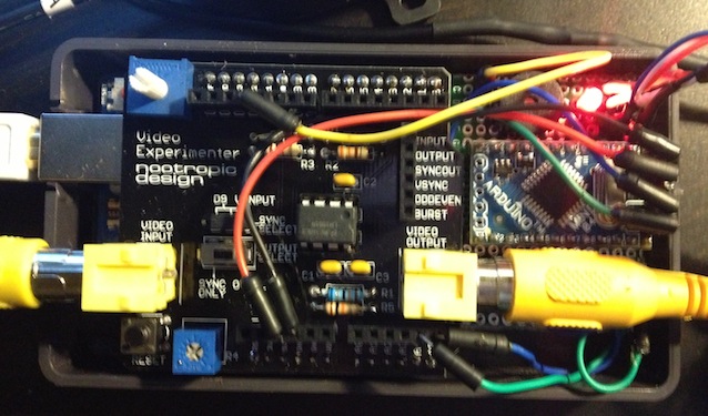
Here is how you wire up the two Arduinos together. Notice that I have an Uno and a Mini hooked up to each other. I’d like to use two Minis instead, however the VE shield is designed for an Uno and there are a lot of project enclosures out there that let you put an Uno and a Mini next to each other in one box. For now, the other components (sensors, buzzer, LEDs) aren’t hooked up. That will come in Part 3.
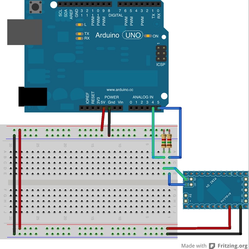
It’s very simple. The resistors are both 1.5K, but you can use anything up to 47k. I2C uses analog pins A4 and A5, so connect them together (A4 to A4, and A5 to A5). You don’t have to use the exact +5V and G pins that I used, I just like to make things look complicated 
Code
The code is equally simple. First, we’ll edit the code on the Mini, the one that reads the sensors.
Sender
Start by adding the following imports:
#include <Wire.h>
#include <EasyTransferI2C.h>
Now we need to define a struct that will represent the data. We will be sending three things: sensor group (rear or front), sensor ID and sensor value:
EasyTransferI2C ET;
struct SENSOR_DATA {
int group;
int id;
int value;
};
SENSOR_DATA sensorData;
Add the following defines as well:
#define I2C_SLAVE_ADDRESS 9
#define DUMMY_PACKET_INTERVAL 250
Ok, you’re ready to set up the EasyTransfer:
void setup() {
Wire.begin();
ET.begin(details(sensorData), &Wire);
}
And now the really hard part:
void sendSensorData(int group) {
sensorData.group = group;
sensorData.id = data[group][SENSOR_ID] - 128;
sensorData.value = data[group][SENSOR_VALUE];
ET.sendData(I2C_SLAVE_ADDRESS);
}
Don’t forget to actually call the “sendSensorData” function. You do that within “updateSensorValue” function:
void updateSensorValues() {
readPins();
for (int i = 0; i < 2; i++) {
if (changed[i]) {
changed[i] = false;
sendSensorData(i);
lastChange = millis();
}
}

// Sends a dummy packet every 250 ms just to keep things talking
if (millis() - lastChange > DUMMY_PACKET_INTERVAL) {
sensorData.id = 255;
sensorData.value = 255;
sendSensorData(255);
lastChange = millis();
}
}
Notice that we send a dummy packet every 250 ms just to keep things going. It helps, on the receiving end, to get these packets because otherwise the loop will block on ET.receive() and you will not be able to expire out old sensor values if they haven’t been updated in a while. More on that later..
You’re done with the sender! Now you have a complete sketch for the sensor interpreter. You can download the full sketch for the Mini here.
Receiver
On the receiving end, things are equally simple. Define the following:
#include <Wire.h>
#include <EasyTransferI2C.h>

#define I2C_SLAVE_ADDRESS 9

EasyTransferI2C ET;
struct SENSOR_DATA {
int group;
int id;
int value;
};
SENSOR_DATA sensorData;
Add the setup function:
void setup() {
Wire.begin(I2C_SLAVE_ADDRESS);
ET.begin(details(sensorData), &Wire);
Wire.onReceive(receive);
}
You also need to add this function, because the library requires it. It gets called every time you receive a packet, though you don’t need to use it. I have it turning on a debug LED:
void receive(int numBytes) {
digitalWrite(DEBUG_LED, !digitalRead(DEBUG_LED));
}
And the loop:
void loop() {
if(ET.receiveData()) {
// Do stuff here
}
}
Congratulations! You should now be receiving sensor data on your second Arduino. In Part 3 I will describe how to use the VE shield to overlay this info onto the composite reverse camera signal.


Hello Adrian,This is my firs Arduino and I also want to make exactly the same thing as you did but i have smteblud across a serios of problems because some of the code that I am using in my arduino is writen in romanian and I don’t know exactly what to change in my code.Could you please help me ? The thing is that my arduino has Temperature, Humidity, Pressure and light sensor and there is a lot of code I must go through.Kind Regards,Flaviu Vlaicu