I’m currently busy creating an Arduino steering wheel adapter between my ’05 Pontiac GTO steering wheel controls and the Parrot Asteroid Smart Android-powered head unit. Doing this because my car isn’t supported by Parrot’s Unika steering wheel control interface, and also because it’s a fun project that’s going to cost me almost nothing and allow for better customization.
Resistance Ladder
The steering wheel controls of my Pontiac GTO are set up as a resistance ladder. Pressing each button changes the resistance between two wires going to the stereo. This is actually a very simple circuit. Each button has a resistance value, like so:
| Button Function | Resistance (Ohm) | |
| Mute | 284 | |
| Volume Up | 164 | |
| Volume Down | 82 | |
| Mode | 1474 | |
| Next Track | 794 | |
| Previous Track | 464 |
And when no button is pressed, the resistance is about 3674 Ohm. You can see where this is going. We need to teach Arduino how to interpret resistance values.
Test Rig
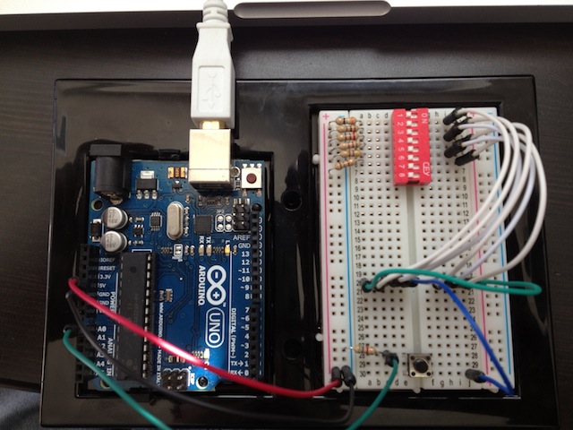
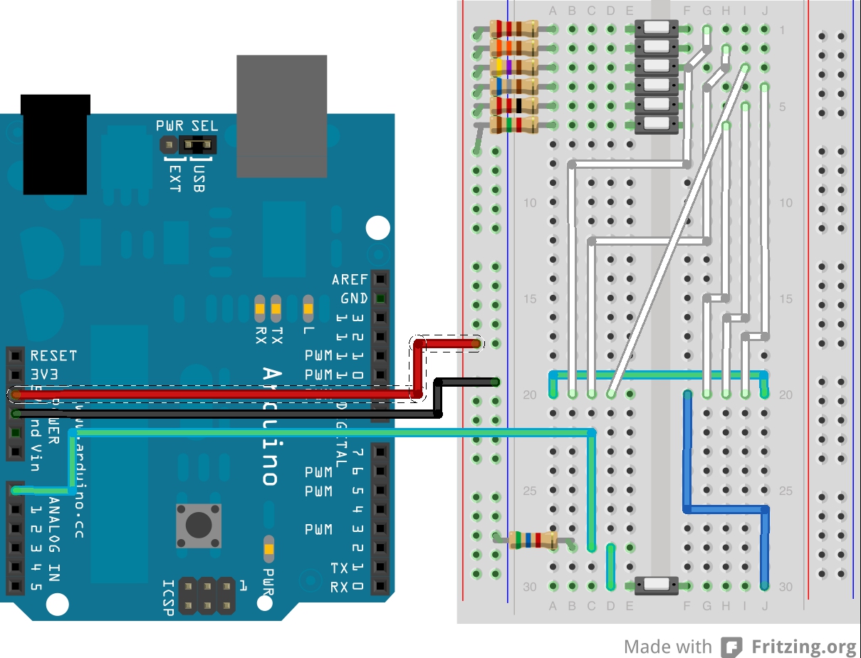
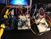
I don’t have a bunch of push buttons that can go on a breadboard, so I made my “steering wheel button simulator” test rig using one push button and a bunch of dip switches. I’ve added six resistors of various values to simulate different buttons (all under 2k Ohm) and a 5.6 KOhm reference resistor. Here’s a picture:
Ok so I know it’s a bit more complicated than what it should be, but I’m lacking parts here, so bear with me.
Arduino Code
The circuit you see above is basically a basic voltage divider. You connect the known resistor (5.6K in this case) to the ground and an unknown resistor (one of the six pictured) to power. You connect the two resistors together and measure the voltage between:
G —— R: 5.6K —— To Arduino —— R: unknown —— Vcc (+5V)
None of these values have to be exact. As you can see in the code, everything is configurable. You can run any voltage you want (that the Arduino will support) and any reference resistor. I picked 5.6K because I like that number, it reminds me of strawberries.
Constants
We’re going to need some constants. Here’s what I have set up for my ’05 Pontiac GTO (resistance values currently match the test rig though):
/* !!! Comment out to stop serial prints.  Do this before flashing HID firmware !!! */
#define DEBUG

#define TOTAL_BUTTONS 6          // Total buttons on the steering wheel
#define NONE -1                  // When no button is pressed
#define MUTE 0                   // Index corresponding to the MUTE button resistance
#define VOLUME_UP 1              // Index corresponding to the VOLUME_UP button resistance
#define VOLUME_DOWN 2            // Index corresponding to the VOLUME_DOWN button resistance
#define MODE 3                   // Index corresponding to the MODE button resistance
#define NEXT 4                   // Index corresponding to the NEXT button resistance
#define PREVIOUS 5               // Index corresponding to the PREVIOUS button resistance

#define TOLERANCE_PERCENT 10.f    // Match tolerance
#define RESISTANCE_PIN 0          // Analogue Input on Arduino
#define R_KNOWN 5600.f            // The known resistor
float VOLTS_IN = 5.f;             // Vcc (+5 Volts)

/* Button resistance values and indexes {MUTE, VOLUME_UP, VOLUME_DOWN, MODE, NEXT, PREVIOUS} */
float BUTTONS[TOTAL_BUTTONS] = {390.f, 100.f, 270.f, 820.f, 470.f, 1800.f};
What’s configurable here? Well, you can change your reference resistor value, your voltage (which will probably always be +5V), button resistance value, number of buttons, which buttons represent what function and the tolerance percentage. The last one (tolerance) determines how close the current measurement has to come to a pre-defined steering wheel control resistance value before being considered a button press.
Variables
These will change over time:
int currentButton = NONE;        // Currently selected button
int rawVolts = 0;                // The raw analogue value
float voltsOut = 0.f;            // Voltage at point between resistors
float resistance = 0.f;          // Unknown resistance.
Here we store the currently selected button, current resistance, voltage, etc.
Measuring Resistance
Define a function that will convert the input voltage to resistance (and a function that prints it):
// Calculates the resistance.
void calculateResistance() {
rawVolts = analogRead(RESISTANCE_PIN);            // Read in raw value (0-1023)
voltsOut = (VOLTS_IN/1024.0) * float(rawVolts);    // Convert to voltage
resistance = R_KNOWN*((VOLTS_IN/voltsOut) - 1);    // Calculate the resistance
}

// Prints the resistance (if DEBUG is enabled)
void printResistance() {
#ifdef DEBUG
Serial.print("Voltage: ");
Serial.print(voltsOut);
Serial.print(", Resistance: ");
Serial.println(resistance);
#endif
}
Detecting Button Presses
These two functions will detect which button has been pressed (and print it):
// Detects which button is currently pressed.
void detectCurrentButton() {
for (int i = 0; i < TOTAL_BUTTONS; i++) {
if (buttonPressed(BUTTONS[i])) {
currentButton = i;
break;
} else {
currentButton = NONE;
}
}
}

// Prints the current button, only if DEBUG is enabled.
void printCurrentButton() {
#ifdef DEBUG
Serial.print("Current Button: ");
switch(currentButton) {
case MUTE:
Serial.println("MUTE");
break;
case VOLUME_UP:
Serial.println("VOLUME_UP");
break;
case VOLUME_DOWN:
Serial.println("VOLUME_DOWN");
break;
case MODE:
Serial.println("MODE");
break;
case NEXT:
Serial.println("NEXT");
break;
case PREVIOUS:
Serial.println("PREVIOUS");
break;
default:
Serial.println("NONE");
}
#endif
}

// Determines if the current resistance is within tolerance of a button resistance.
boolean buttonPressed(float buttonResistance) {
float decimalPercent = TOLERANCE_PERCENT / 200.f;
float highRange = buttonResistance * (1.f + decimalPercent);
float lowRange = buttonResistance * (1.f - decimalPercent);
return lowRange <= resistance && resistance <= highRange;
}
Wrapping Up
Now add the following setUp() and loop() functions:
void setup() {
Serial.begin(9600);
}

void loop() {
calculateResistance();
printResistance();
detectCurrentButton();
printCurrentButton();
delay(1000);
}
And try different buttons! The serial monitor should show something like this:
Vol, Resistance: inf
Current Button: NONE
Voltage: 4.68, Resistance: 385.80
Current Button: MUTE
Voltage: 4.91, Resistance: 100.20
Current Button: VOLUME_UP
Voltage: 4.77, Resistance: 275.41
Current Button: VOLUME_DOWN
Voltage: 4.61, Resistance: 474.58
Current Button: NEXT
Voltage: 3.78, Resistance: 1808.79
Current Button: PREVIOUS
Source Code
Download the full sketch here. Don’t forget to change the resistance values to adapt to your particular steering wheel. This will work on any resistance ladder type control, so if your car isn’t a Pontiac GTO you just need to fiddle the values and add/remove buttons to match your car’s controls.








Hi, it’s great to see your progress! I have received my Teensy 2.0 board today from http://pjrc.com/teensy/index.html
Was up and running in about 10 minutes – the author of this little board got all the pieces right – two development platforms are available (Arduino and cross-compiler AVR gcc with toolchain). It’s completely host platform agnostic – works in MacOS, Linux and Windoze. He has USB HID support (no special firmware is required). Bootloader has ability to download firmware images from host and there’s a HID debug application available for host (works on MacOS, Linux and Windoze). It’s so easy to develop on, it’s getting almost to the point of being boring!
The main challenge for me is now to figure out pin-out of rotary encoder with built-in D-pad I have scored from my trash bin. Can you share the keycodes you are sending to control apps on Parrot Smart?
-albertr
I need that. I currently have to take the dash apart to change the loaded sketch due to having to put the Uno in DFU mode.
Ahh, almost forgot to add that for HID it has LUFA support: http://www.fourwalledcubicle.com/files/LUFA/Doc/130303/html/_page__build_module__h_i_d.html
-albertr
Nice! Yeah, I’ve been driving with fully functional steering wheel controls and it’s been great! Just haven’t had time for a full writeup. Here’s how things work on mine:
1) Use HID keycodes for volume and d-pad control:
2) Media HID keycodes don’t work, but you can work around that using Tasker. In fact, using Tasker you can map any button to any action. You just create a task of what you want to do (media next, play/pause, previous, day mode, etc) and then go to Manage Application > Quick Launch. There you hit Menu and select Shortcut, then select the Tasker task. So you can effectively map things to a combination of Search+ to do any task. For example, you can map Search+N to go to the next track.
To send multiple keycodes I’m doing the following:
uint8_t buffer[8] = {0};
...
buffer[2] = 0x0065; // Search modifier key
buffer[3] = 0x0011; // Character N key
Serial.write(buffer, 8);
Works like a charm. Check out this video:
Looking good! Thanks alot for sharing it, I’m hoping to get some time this weekend to wire it up and looking forward to use your findings.
-albertr
Thanks for sharing it. Unfortunately, I was totally swamped this weekend, will try to wire it up next Saturday.
-albertr
how do things look when connected to your wiring harness?
G —— R: 5.6K —— To Arduino —— SWC —— Vcc (+5V) ?
Mike, the Arduino USB port is plugged into the stereo via the USB port and programmed to present itself as an HID keyboard as described here: http://atomic-cactus.com/2013/03/26/parrot-asteroid-smart-steering-wheel-controls-using-arduino-part-1/
Where the Arduino connects to the factory stereo harness to get steering wheel control input is the same place you would connect an aftermarket steering wheel controls adapter, like the “PAC SWI-JACK”. Here are the instructions specific to 04-06 GTO: http://www.ls1gto.com/forums/showpost.php?p=5696281&postcount=4
In other words, what you posted is correct. The green wire in my diagram and breadboard picture is what gets connected to one of the steering wheel control wires, the other wire gets Vcc.
G —— R: 5.6K —— To Arduino —— C11 (brown wire)

C12 (black/yellow wire) —— Vcc (+5V on the Arduino board)
This is awesome! My Arduino is on the way. For the cost of the Unika I can buy 4 Arduinos! I’m running out of USB ports though. Have you tested using a USB hub with the Asteroid Smart?
I haven’t tried a hub, no. Wondering that myself.
Awesome blog Yuri, I’m looking into trying to get the steering wheel controls working on my 2013 corvette, but I’m trying to find the easiest way. Would something like this work without having to solder wires or program the arduino board? http://www.cartft.com/catalog/il/1552 another link http://store.mp3car.com/Joycon_EXR_Steering_Wheel_Control_PC_Interface_p/com-159.htm
I’ve never messed with arduino boards, but worst case scenario I’m sure I could figure it out, just wondering if that JoyCon would work, if so it would be a lot simpler…
Wow, that’s cool! Yeah, it’ll work. The trick is programming in the necessary keystrokes, like a combination of “Search+key” to activate quick-launch shortcuts that are Tasker tasks (this is how mine currently works to switch songs, activate voice control, etc). Reading the description, it looks like it’ll work for that purpose, you’ll just need the key codes. Nice find!
Yuri, I got the JoyCon Exr to work, but so far I only have the volume up, volume down, Home, Back, and kind of a mute button working. For mute I had to use volume down, but the joycon has an S-Hold setting that repeats the button press, so it just lowers the volume down, it doesn’t raise it back up, but I can live with that. I haven’t been able to figure out if there is a mapping for a search key on the JoyCon Explorer app. I would like to get next and previous working, along with an actual mute (tasker turning silent mode on/off?).
For the Search modifier key, the code is 0x0065. This corresponds to the following button under the HID usage table:
http://www.freebsddiary.org/APC/usb_hid_usages.php
Once you get quicklaunch shortcuts working, you’ll be able to have a working mute button if you use tasker.
The one thing that really bugs me about the Parrot Asteroid SMART is the lack of physical volume control buttons. My car doesn’t have steering wheel audio controls, so UNIKA is not a possibility. Parrot make a bluetooth steering wheel remote for the Asteroid tablet, but it won’t work on the SMART (they say it will later this year).
I stumbled across your work here, and have my own similar project (open source on github – https://github.com/markwj/hidmedia).
Using a PIC18F2550 (US$6 @mouser) usb-capable micro controller, I threw together a workable hand built prototype. It has a d-pad, two function keys and a mode switch. At the moment, I’ve got it programmed as mode 0 directional control and mode 1 media control. In directional control mode, it behaves like up, down, left, right, enter, esc, menu, etc – useful for navigating around the Android screens. In media control mode, the two top buttons are volume decease/increase, and the others will be for previous song, next song, play/pause, stop, mute, etc. There is a little led that currently blinks when you press a key.
I couldn’t get HID keyboard volume keys to work reliably, so switched to the consumer profile vol- and vol+ which work well for me. My code supports both consumer and keyboard profiles. I couldn’t get consumer or keyboard media control responding, but found your comments here about using Tasker and SEARCH+code to launch actions. Brilliant solution and gets the media control working well. The little tasker ‘flash’ popups for mode switch are also really cool and will allow more modes to be added (my first work had a toggle switch – mode 0 or mode 1).
Still some tuning to do, but not bad for a few hours work at the weekend.
Last thing would be to 3D print a nice box, but for the moment it works ok wrapped in black tape:
http://www.teslamotorsclub.com/attachment.php?attachmentid=21531&d=1367747866
That’s really cool! Looks like there are quite a few HID based solutions out there these days, perhaps they all deserve their own blog post or something. Do you have your project documented anywhere? I’d be happy to link to it. Adding extra hardware controls for cars that don’t have factory steering wheel buttons can get tricky. I like that yours switch layouts, I did the same thing on mine with D-Pad and Media layouts. Surprisingly D-Pad works really well on the Asteroid.
My project description, links, and code are all here:
https://github.com/markwj/hidmedia
I spent another hour on the software last night. Got a workable debounce and long-press logic in place, and re-worked the hardware to use software mode control (the tasker flash notifications work really well for notification of which mode you are in). With 7 keys, both long and short presses, I now get 14 combinations per mode. Plenty for what I need to do.
Long press on the centre d-pad button bring up utter voice control. Neat.
I couldn’t get the consumer control MUTE to work, or tasker media control Prev or Next Song. Not sure what is going on there – I need to spend more time in the car working on it.
You can probably set up a MUTE toggle using Tasker. Just use the if-else flow controls to lower the media volume and bring it back up. Might require storing the current volume level in a separate variable in Tasker.
Yuri,
Have you had any luck with the Previous Song, Next Song controls in Tasker? I can’t get mine to work.
The task run, but seems to switch to some internal media player that plays from the SD card. Once that has started, none of the internal media players work anymore (e.g.; spotify, asteroid music, etc) – they just won’t play / pause the song unless the unit is rebooted.
I’m using the standard tasker media control with simulated media keys.
Yes, I got them to work. BUT, there’s a caveat. You can’t have any other media players installed. No Pandora, no Google Music, no Winamp, etc. Otherwise, those applications will intercept all next/previous button presses. Unfortunately that’s the only way around it. For me this works fine, because I only play music from a USB drive and occasionally via Bluetooth. The default ASTEROID media player is very glitchy when it comes to media controls, but if you don’t have any other media players installed they work consistently. Unfortunately, I have not been able to find a way around that yet.
Hello is this be work on Asteroid classic and Ford steering ?
From what I’ve been reading about the classic, I don’t see why not. As long as the Ford vehicle uses a resistor ladder for steering wheel buttons.
hello again i testing arduino whith two buttons on my asteroid classic and it works ok
but if i write to arduino yours “resistance.ino” sketch ant than put it to HID by DFU something is wrong the keyborad is some crazy on the compter and on the asteroid. i change the resitance and i dont now what is wrong
Great project! I am interested in doing the same thing on my Saturn with an aftermarket Ouko head unit. On my head unit there is a CAN bus RX and a CAN BUS TX. Are these the same wires you were working with on your project? I want to do one variant to what you did. I want to integrate this project with voice control using a SpeakUp click Board made by MikroElektronika. This is a cool device. Really simple to use. I was going to configure the output of the Speak up board to feed a binary input to the Arduino and then have the Arduino translate the signal to the CAN Bus of the Head unit.
Should definitely work. Best of luck! I’m currently trying to replicate this with a CAN-BUS Arduino shield on a Land Rover LR2.
To answer your question, the steering wheel controls on my old Pontiac GTO were no wired to the CAN bus. They were simple resistors, so not quite the same wires. But there’s no reason why it wouldn’t work with an Arduino capable of reading CAN messages.
I’m trying to use this to capture the resistance value of steering wheel cruise control on/off button to trigger the old on/off button via another output on the board. But I’m not a arduino coder only done a little with it. It needs to detect a continuity of less than 2 Ohm.
You will need to use a lower resistance value for the resistor. This seems really low to me, though. At such a lot resistance you may get too many false-positives due to voltage fluctuations in the electrical system. You may need to build a specialized circuit to detect resistances so low.
Nice work on the Asteroid Smart. I have a rather strange question though. I am wondering if the opposite would be possible. Could you use a USB controller and an arduino board to send signals to an ASWC-1 steering wheel control adapter to control a headunit? I am looking to add a USB volume knob and somehow get a stereo to detect it. I no longer have a Asteroid Smart but thought you’d be a good person to ask.
Yes, I don’t see why not. A regular Arduino would be detected by the Android OS as a serial port. You should be able to write to it. You’d probably need a separate app to do that, or at the very least a shell script. But you should be able to send commands to Arduino that way. And the Arduino would then relay them to the steering wheel adapter.
The trick is knowing what to send to the ASWC-1 adapter, that may require some reverse-engineering. Good luck!
This was a really great write-up; I was able to duplicate everything on my Pro Micro in very little time.
But what next? How do I move from here to actually sending keyboard commands via the arduino?
I have the same problem… : / Dunno what command to send for the Asteroid to get keyboard commands or audio commands (volume up, down, next, prev, etc..) frustrating.
Hi , very cool project. Maybe you can help me ?
I try to reactivate my steering wheel remote with an arduino pro micro. It is resistance controlles and uses 2 “rows” (A0 / A1) with 4 buttons in each row (total of 8, each has its own resistance value) is there any option to convert your code for using it as a keyboard ? I tried various sketches and i have readings on A0 and A1 , so the breadboard construction works, but i have no clue to get it working on an arduino (I am very new to this). It would be enough when the buttons on the RC “press” keys 1,2,3,4,5,6,7,8 as a keyboard emulator (no special keys needed). Thank you
Hi, it’s been a while since I’ve maintained the blog or replied to comments (sorry about that!) but, yes, it should work. You want to measure the max and min resistance of your buttons first, then use an online resistance calculator to scale the voltage from these so that it falls between what an Arduino can read (usually from 0 to 5 volts). You’ll need to modify the sketch to capture these readings as “ranges” of voltage readings.
I know it probably sounds vague, but as long as you can convert the voltage coming off the steering wheel into a 0v to 5v signal, you should be able to get the Arduino to recognize the buttons. Hope this helps!