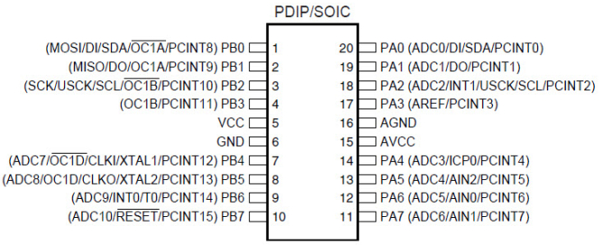
I’ve been needing to use an AVR controller with a lot of GPIO to receive commands over Serial and control two servos (along with a few other devices). One thing I noticed after building the PCB is that there aren’t a whole lot of libraries available for servo control for the x61 series because this chip has a really weird 10-bit timer, while most other chips have either an 8-bit or 16-bit timer.
8-bit timers aren’t great for servo control because their resolution limits your range of motion. If you want to rotate the servo from 0 to 180 degrees, you may be limited to rotating 2-3 degrees at a time, instead of the 1 degree increments. For some this may be fine, but for my application I wanted to maximize the resolution. Another problem with 8-bit libraries is that they typically use Timer1 interrupts to pulse servos. If your chip isn’t doing much more than just running the servos, that’s not a big deal. But if you plan on using Serial, and do other things – you’re going to quickly notice that Timer1 interrupts interfere with the chip’s operation. For example, on the x61 the Serial is implemented in software and uses pin change interrupts, which themselves can get interrupted by your servo timer. You end up with working servos, but unusable Serial comms.
So with that in mind, I’ve set out to figure out how to use hardware PWM to drive two servos without using Timer1 interrupts. You’ll notice that the chip has 3 PWM pins (OC0A, OC1B, OC1D). The pins we’ll be using here are OC1B (PB3) and OC1D (PB5). These pins are directly connected to the servo’s signal wires.


Recent Comments