• Servo control with AVR ATTiny x61 (261/461/861) Servo control with AVR ATTiny x61 (261/461/861)

    Servo control with AVR ATTiny x61 (261/461/861)

Servo control with AVR ATTiny x61 (261/461/861)

I’ve been needing to use an AVR controller with a lot of GPIO to receive commands over Serial and control two servos (along with a few other devices). One thing I noticed after building the PCB is that there aren’t a whole lot of libraries available for servo control for the x61 series because this chip has a really weird 10-bit timer, while most other chips have either an 8-bit or 16-bit timer.

8-bit timers aren’t great for servo control because their resolution limits your range of motion. If you want to rotate the servo from 0 to 180 degrees, you may be limited to rotating 2-3 degrees at a time, instead of the 1 degree increments. For some this may be fine, but for my application I wanted to maximize the resolution. Another problem with 8-bit libraries is that they typically use Timer1 interrupts to pulse servos. If your chip isn’t doing much more than just running the servos, that’s not a big deal. But if you plan on using Serial, and do other things – you’re going to quickly notice that Timer1 interrupts interfere with the chip’s operation. For example, on the x61 the Serial is implemented in software and uses pin change interrupts, which themselves can get interrupted by your servo timer. You end up with working servos, but unusable Serial comms.

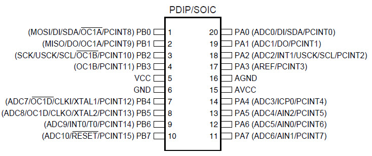
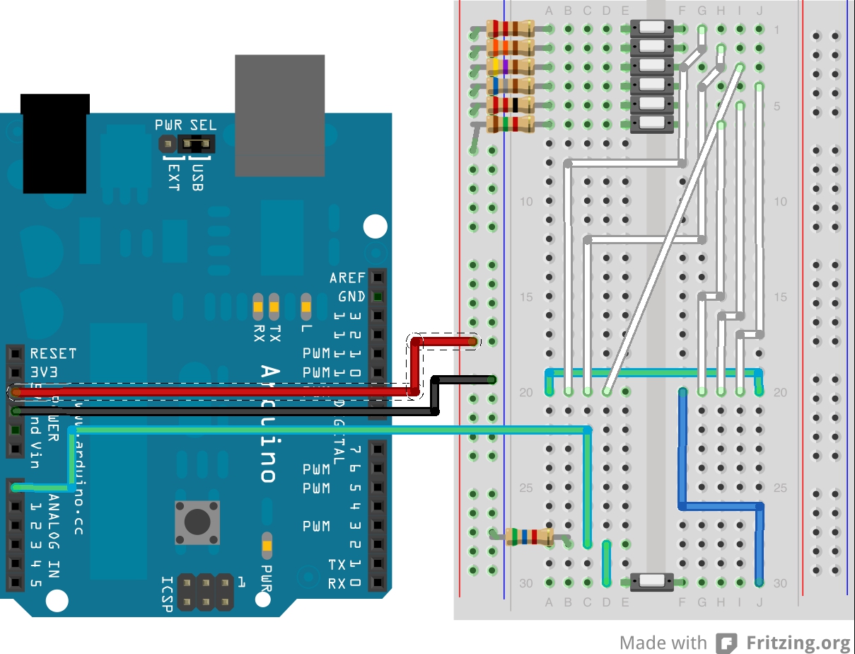
So with that in mind, I’ve set out to figure out how to use hardware PWM to drive two servos without using Timer1 interrupts. You’ll notice that the chip has 3 PWM pins (OC0A, OC1B, OC1D). The pins we’ll be using here are OC1B (PB3) and OC1D (PB5). These pins are directly connected to the servo’s signal wires.

  • Raspberry Pi Read-Only File System Raspberry Pi Read-Only File System

    Raspberry Pi Read-Only File System

Raspberry Pi Read-Only File System

There are many reasons to make your file system read-only. The primary reason is to prevent file system corruption from sudden shutdowns. I’ve been building a Raspberry-Pi consumer device for the past year and this was one of the requirements: the user should be able to unplug the device while running, with zero consequence. See my other post on how to move /tmp to RAM. This is a continuation of that discussion.

My information comes from the following posts:

http://blog.pi3g.com/2014/04/make-raspbian-system-read-only/

http://openenergymonitor.org/emon/node/5331

sudo cp /etc/default/rcS /etc/default/rcS.orig
sudo sh -c "echo ‘RAMTMP=yes’ >> /etc/default/rcS"
sudo mv /etc/fstab /etc/fstab.orig
sudo sh -c "echo ‘tmpfs /tmp tmpfs nodev,nosuid,size=30M,mode=1777 0 0’ >> /etc/fstab"
sudo sh -c "echo ‘tmpfs /var/log tmpfs nodev,nosuid,size=30M,mode=1777 0 0’ >> /etc/fstab"
sudo sh -c "echo ‘proc /proc proc defaults 0 0’ >> /etc/fstab"
sudo sh -c "echo ‘/dev/mmcblk0p1 /boot vfat defaults 0 2’ >> /etc/fstab"
sudo sh -c "echo ‘/dev/mmcblk0p2 / ext4 defaults,ro,noatime,errors=remount-ro 0 1’ >> /etc/fstab"
sudo sh -c "echo ‘ ‘ >> /etc/fstab"
sudo mv /etc/mtab /etc/mtab.orig
sudo ln -s /proc/self/mounts /etc/mtab

Now create the following two sripts in /usr/bin

sudo nano /usr/bin/rpi-rw

#!/bin/sh
sudo mount -o remount,rw /dev/mmcblk0p2 /
echo "Filesystem is unlocked – Write access"
echo "type ‘ rpi-ro ‘ to lock"

sudo nano /usr/bin/rpi-ro

#!/bin/sh
sudo mount -o remount,ro /dev/mmcblk0p2 /
echo "Filesystem is locked – Read Only access"
echo "type ‘ rpi-rw ‘ to unlock"

sudo chmod +x /usr/bin/rpi-rw
sudo chmod +x /usr/bin/rpi-ro

After creating the two scripts above, you can now type rpi-rw to make the system temporarily writable, and rpi-ro to lock it down again.

  • Raspberry Pi – Moving /tmp to RAM Raspberry Pi – Moving /tmp to RAM

    Raspberry Pi – Moving /tmp to RAM

Raspberry Pi – Moving /tmp to RAM

Sometimes you want to make sure that any file operations OS does don’t corrupt your file system because of a sudden shutdown. The most common culprit is usually the /tmp folder. Adding the following lines of code to your fstab will make the OS write any temporary files to RAM. This not only saves your SD card from multiple writes, but makes sure that, given no other file system activity, you can just unplug your Pi without consequences:

sudo nano /etc/fstab

tmpfs /var/log tmpfs defaults,noatime,nosuid,mode=0755,size=100m 0 0
tmpfs /tmp tmpfs defaults,noatime,nosuid,size=100m 0 0
tmpfs /var/tmp tmpfs defaults,noatime,nosuid,size=30m 0 0
tmpfs /var/log tmpfs defaults,noatime,nosuid,mode=0755,size=100m 0 0
tmpfs /var/run tmpfs defaults,noatime,nosuid,mode=0755,size=2m 0 0
tmpfs /var/spool/mqueue tmpfs defaults,noatime,nosuid,mode=0700,gid=12,size=30m 0 0

I’m posting this with a caveat: I’m no Linux expert. But this, along with making the entire file system (save for a few special folders) read-only, allowed me to build a Raspberry Pi project which can be unplugged at any time while running without any file system corruption. I’ll be making a separate post on how to make the file system read-only in Raspbian very soon.

  • Power Cycling Raspberry Pi USB Hub Power Cycling Raspberry Pi USB Hub

    Power Cycling Raspberry Pi USB Hub

Power Cycling Raspberry Pi USB Hub


This is going to be my first post in a long time. Long story short: got married, got fat, got divorced. Back to tinkering with hardware 🙂

I’ve recently been engaged on a project that involves Raspberry Pi and computer vision. The computer vision part is accomplished via a cheap USB cam, using the UVC video driver that ships with most Linux distros. After turning the camera on and off multiple times I noticed that I started getting garbage over the wire. Unplugging the camera and plugging it back in always solved the problem. So I decided to find a way to programmatically power-cycle a specific USB device using a shell script, which I could invoke from my Java code. Here’s what worked for me:

First, you need to allow permissions to power cycle USB devices. I used a VERY CRUDE method, because I’m a noob and decided to abuse chmod:

# Allow USB power cycling via software
sudo chmod 777 /sys/bus/usb/drivers/usb/bind
sudo chmod 777 /sys/bus/usb/drivers/usb/unbind

Once you do this, your application (and ANY application) can now address the RPi’s USB hub. You can shut down individual devices, or the entire hub. Look up how USB device addressing works. If you’re not sure, you can print out what the specific device addresses for the driver you’re using (in my case it’s uvcvideo)

# Print out USB ports to which the camera is connected
echo ‘Device locations:’
ls /sys/bus/usb/drivers/uvcvideo/ | grep ‘1-‘

And here’s the golden nugget. This is how you power cycle a specific USB port:

nano power_cycle_usb.sh

#!/bin/sh
echo ‘Device locations:’
ls /sys/bus/usb/drivers/uvcvideo/ | grep ‘1-‘
echo ‘Unbinding device’
echo ‘1-1.2’ > /sys/bus/usb/drivers/usb/unbind
sleep 0.5
echo ‘Binding device’
echo ‘1-1.2’ > /sys/bus/usb/drivers/usb/bind
echo ‘Power cycle complete’

I’ve tested this for months. Works every time. Just be careful which device you power cycle, because the Ethernet […]

  • Parrot Asteroid Smart – Day/Night Toggle w Tasker Parrot Asteroid Smart – Day/Night Toggle w Tasker

    Parrot Asteroid Smart – Day/Night Toggle w Tasker

Parrot Asteroid Smart – Day/Night Toggle w Tasker

Been a while since my last post. I went on vacation right after my car got rear-ended. Now that I got it back, I wanted to share a few tweaks that I’ve made to make my life easier, starting with the day/night mode toggle using Tasker. It’s quite simple, actually. It can pretty much be described with a series of screenshots. First, create a new Task, and call it something descriptive. In the task, add an item from “Tasker” called “If”, and select “Night Mode”, then set it to match “on”. After adding this, add two more tasks underneath like so:

Nest, add a similar “Else” statement. This will ensure that if the Night Mode is “on” then it will switch to Day Mode, and otherwise it’ll switch back to Night Mode. In Tasker, this is called “Flow Control”:

Lastly, test by pressing the “play” button on the top left corner of the screen. You should be able to toggle between day and night modes easily:

If you want to place this as an icon on your home screen (or assign it to a quick launch shortcut if you use steering wheel controls), you will need to click the bottom right icon and select an icon for this task. Once done, go to your launcher and add a Tasker “Task Cut” shortcut. You can then customize how it looks and you’ll be able to click it to switch modes. Mine is assigned to a steering wheel […]

  • Resistor Ladder Steering Wheel Control Interpreter Using Arduino Resistor Ladder Steering Wheel Control Interpreter Using Arduino

    Resistor Ladder Steering Wheel Control Interpreter Using Arduino

Resistor Ladder Steering Wheel Control Interpreter Using Arduino

I’m currently busy creating an Arduino steering wheel adapter between my ’05 Pontiac GTO steering wheel controls and the Parrot Asteroid Smart Android-powered head unit. Doing this because my car isn’t supported by Parrot’s Unika steering wheel control interface, and also because it’s a fun project that’s going to cost me almost nothing and allow for better customization.

Resistance Ladder

The steering wheel controls of my Pontiac GTO are set up as a resistance ladder. Pressing each button changes the resistance between two wires going to the stereo. This is actually a very simple circuit. Each button has a resistance value, like so:

Button Function   Resistance (Ohm)
Mute   284
Volume Up   164
Volume Down   82
Mode   1474
Next Track   794
Previous Track   464

And when no button is pressed, the resistance is about 3674 Ohm. You can see where this is going. We need to teach Arduino how to interpret resistance values.

Test Rig

I don’t have a bunch of push buttons that can go on a breadboard, so I made my “steering wheel button simulator” test rig using one push button and a bunch of dip switches. I’ve added six resistors of various values to simulate different buttons (all under 2k Ohm) and a 5.6 KOhm reference resistor. Here’s a picture:

steering-test-rig

steering_bb

Ok so I know it’s a bit more complicated than what it should be, but I’m lacking parts here, so bear with me.

Arduino Code

The circuit you see above is basically a basic voltage divider. You connect the known resistor (5.6K in this case) to the ground and an unknown resistor (one of the six pictured) to power. You […]

  • Parrot Asteroid Smart – Root Access Parrot Asteroid Smart – Root Access

    Parrot Asteroid Smart – Root Access

Parrot Asteroid Smart – Root Access

Good news, everyone! You can root your Parrot Asteroid Smart head unit. The entry that’s going to follow this one will describe how to install the Google Play store and spoof your device identity so you can download all of the apps available to most Android devices out there. But this post is just about rooting. Rooting is, arguably, the easy part. That’s because someone has already figured out a generic root tool for a whole number of devices, which includes the Smart. I take no credit for this work.

Rooting

Rooting is the easy part of this process. The first thing you will need is to download a tool called Framaroot from here.

Once downloaded, you need to install the Framaroot APK on your device. I used the ADB utility:

./adb install /Users/Yuri\ A/Downloads/APK/Framaroot.apk

Once installed, run the utility and install SuperSU (you’ll have to select it from the drop down menu). It’s *IMPORTANT* that you use SuperSU and not something else:

Reboot the device. Check that you have the SuperSU application now on your device:

You’ll want to run it and ensure that root access is enabled:

Run the following command in on your computer:

./adb shell
su

You should see the “$” change to “#” in the shell, and on your device you should see a confirmation popup asking to grant superuser access to ADB:

That’s it, you have successfully rooted your Parrot Asteroid Smart! Easiest root ever. Thanks to the creator of Framaroot, of course! Stay […]

  • Parrot Asteroid Smart – Steering Wheel Controls Using Arduino – Part 1 Parrot Asteroid Smart – Steering Wheel Controls Using Arduino – Part 1

    Parrot Asteroid Smart – Steering Wheel Controls Using Arduino – Part 1

Parrot Asteroid Smart – Steering Wheel Controls Using Arduino – Part 1

Today I found out that you can plug in a regular HID keyboard into the Parrot Asteroid Smart and it will work. You know what else you can plug in that’s like an HID keyboard? An Arduino!! This means we can begin adding hardware controls to the head unit by mapping keyboard keys to software functions. This also means we can use the Arduino to wire up factory steering wheel controls of cars that are not compatible with Unika (Parrot’s steering wheel control interface). In Part 1 of this tutorial, the goal is to get you to understand how to program the HID keyboard Arduino and at the end you should be able to plug it into your Asteroid Smart and navigate UP and DOWN.

HID Arduino

First things first, you need to turn your Arduino into an HID device. This part is actually fairly easy, though it may be time consuming. The first thing you need is to install a DFU Programmer. Instructions are on the Arduino site, however if you’re on a Mac and you’ve had MacPorts installed, but you’ve switched to Lion and now MacPorts don’t work, here are some tips. ALSO!!!! If you just don’t feel like messing with MacPorts, or you hate it as much as I do , just skip this whole thing and compile the DFU Programmer source manually. It’s probably going to […]

  • Parkonator – Part 3 Parkonator – Part 3

    Parkonator – Part 3

Parkonator – Part 3

This is the final part of the 3-part series about the Parkonator, a device that overlays parking sensor information on top of any RCA backup camera.

Video Overlay

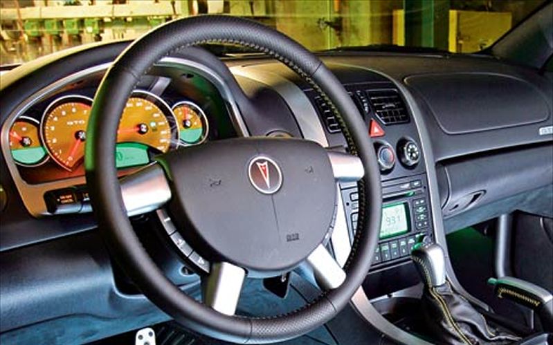
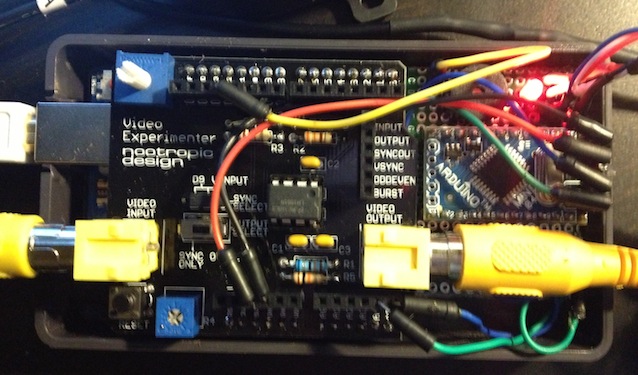
Now that we can get the sensor data to the second Arduino that has control of the Video Experimenter shield, we can start displaying the data. First things first, however. The camera I have picked already draws some sort of alignment lines to help with parking. The trick is to overlay the sensor information in such a way as to “highlight” the objects on camera where they actually are. For this, I’ve set up a test rig. Another important thing is we want to align the data in such a way as to give the user the perception of “tracking” an object. So, looking through the camera as you’re getting closer to something, […]

  • Parrot Asteroid Smart – Side Loading Apps And Customizing The UI Parrot Asteroid Smart – Side Loading Apps And Customizing The UI

    Parrot Asteroid Smart – Side Loading Apps And Customizing The UI

Parrot Asteroid Smart – Side Loading Apps And Customizing The UI

So you’ve purchased your shiny new Parrot Asteroid Smart head unit and are wondering what you can do with it, aside from what’s available from the official Parrot sources? Perhaps there are some minor annoyances that you wish to fix? Then read on. I’ve spent the last few weeks with this head unit and I’m happy to say that I’ve discovered some pretty interesting off-the-shelf apps that’ll make your experience much more pleasant.

Sideloading Apps

So how do you side load apps to the head unit? There are several methods. The one I use is the developer way, where you side load applications using the tools that come with Android SDK downloaded for development purposes. The other method is to load applications from a USB key. Both are really simple and do not require you to root the device. Which is good news, because at the time of typing this nobody has been able to root the Asteroid Smart yet. YET..

Android SDK

Before being able to use the Android dev tools to side load apps, you need to enable a few things on the head unit itself. I’m away from it at the moment, but it goes something like this:

  1. Go to Settings > Applications
  2. Enable installation of applications from unknown sources
  3. Scroll further down to Settings > Applications > Development
  4. Enable USB debugging

You’re now ready. On the back of the unit there’s a USB port with a laptop icon next to it. This is the port you will be using to connect to your computer. Once you’re hooked up, you need to cd into the platform-tools directory inside the SDK folder. There you will […]