• Servo control with AVR ATTiny x61 (261/461/861) Servo control with AVR ATTiny x61 (261/461/861)

    Servo control with AVR ATTiny x61 (261/461/861)

Servo control with AVR ATTiny x61 (261/461/861)

I’ve been needing to use an AVR controller with a lot of GPIO to receive commands over Serial and control two servos (along with a few other devices). One thing I noticed after building the PCB is that there aren’t a whole lot of libraries available for servo control for the x61 series because this chip has a really weird 10-bit timer, while most other chips have either an 8-bit or 16-bit timer.

8-bit timers aren’t great for servo control because their resolution limits your range of motion. If you want to rotate the servo from 0 to 180 degrees, you may be limited to rotating 2-3 degrees at a time, instead of the 1 degree increments. For some this may be fine, but for my application I wanted to maximize the resolution. Another problem with 8-bit libraries is that they typically use Timer1 interrupts to pulse servos. If your chip isn’t doing much more than just running the servos, that’s not a big deal. But if you plan on using Serial, and do other things – you’re going to quickly notice that Timer1 interrupts interfere with the chip’s operation. For example, on the x61 the Serial is implemented in software and uses pin change interrupts, which themselves can get interrupted by your servo timer. You end up with working servos, but unusable Serial comms.

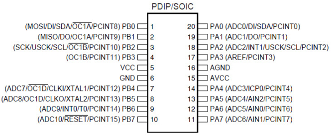
So with that in mind, I’ve set out to figure out how to use hardware PWM to drive two servos without using Timer1 interrupts. You’ll notice that the chip has 3 PWM pins (OC0A, OC1B, OC1D). The pins we’ll be using here are OC1B (PB3) and OC1D (PB5). These pins are directly connected to the servo’s signal wires.

  • Resistor Ladder Steering Wheel Control Interpreter Using Arduino Resistor Ladder Steering Wheel Control Interpreter Using Arduino

    Resistor Ladder Steering Wheel Control Interpreter Using Arduino

Resistor Ladder Steering Wheel Control Interpreter Using Arduino

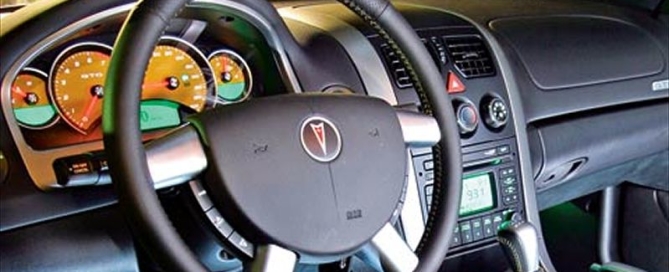
I’m currently busy creating an Arduino steering wheel adapter between my ’05 Pontiac GTO steering wheel controls and the Parrot Asteroid Smart Android-powered head unit. Doing this because my car isn’t supported by Parrot’s Unika steering wheel control interface, and also because it’s a fun project that’s going to cost me almost nothing and allow for better customization.

Resistance Ladder

The steering wheel controls of my Pontiac GTO are set up as a resistance ladder. Pressing each button changes the resistance between two wires going to the stereo. This is actually a very simple circuit. Each button has a resistance value, like so:

Button Function   Resistance (Ohm)
Mute   284
Volume Up   164
Volume Down   82
Mode   1474
Next Track   794
Previous Track   464

And when no button is pressed, the resistance is about 3674 Ohm. You can see where this is going. We need to teach Arduino how to interpret resistance values.

Test Rig

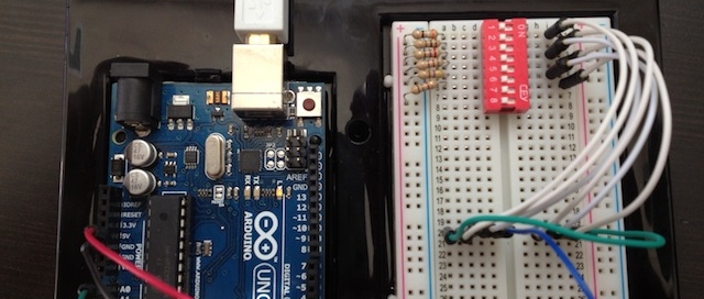
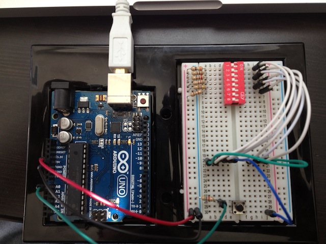
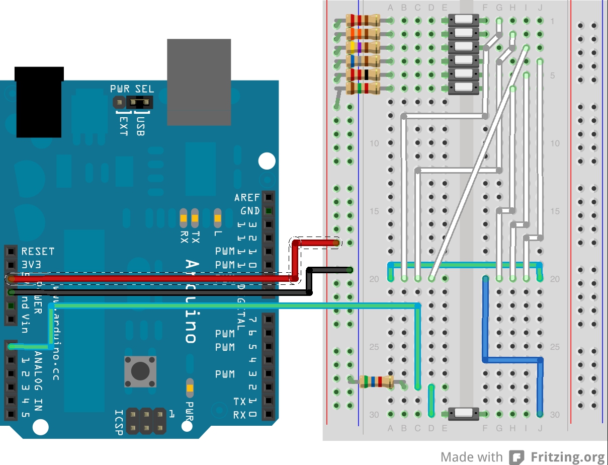
I don’t have a bunch of push buttons that can go on a breadboard, so I made my “steering wheel button simulator” test rig using one push button and a bunch of dip switches. I’ve added six resistors of various values to simulate different buttons (all under 2k Ohm) and a 5.6 KOhm reference resistor. Here’s a picture:

steering-test-rig

steering_bb

Ok so I know it’s a bit more complicated than what it should be, but I’m lacking parts here, so bear with me.

Arduino Code

The circuit you see above is basically a basic voltage divider. You connect the known resistor (5.6K in this case) to the ground and an unknown resistor (one of the six pictured) to power. You […]

  • Parrot Asteroid Smart – Steering Wheel Controls Using Arduino – Part 1 Parrot Asteroid Smart – Steering Wheel Controls Using Arduino – Part 1

    Parrot Asteroid Smart – Steering Wheel Controls Using Arduino – Part 1

Parrot Asteroid Smart – Steering Wheel Controls Using Arduino – Part 1

Today I found out that you can plug in a regular HID keyboard into the Parrot Asteroid Smart and it will work. You know what else you can plug in that’s like an HID keyboard? An Arduino!! This means we can begin adding hardware controls to the head unit by mapping keyboard keys to software functions. This also means we can use the Arduino to wire up factory steering wheel controls of cars that are not compatible with Unika (Parrot’s steering wheel control interface). In Part 1 of this tutorial, the goal is to get you to understand how to program the HID keyboard Arduino and at the end you should be able to plug it into your Asteroid Smart and navigate UP and DOWN.

HID Arduino

First things first, you need to turn your Arduino into an HID device. This part is actually fairly easy, though it may be time consuming. The first thing you need is to install a DFU Programmer. Instructions are on the Arduino site, however if you’re on a Mac and you’ve had MacPorts installed, but you’ve switched to Lion and now MacPorts don’t work, here are some tips. ALSO!!!! If you just don’t feel like messing with MacPorts, or you hate it as much as I do , just skip this whole thing and compile the DFU Programmer source manually. It’s probably going to […]

  • Parkonator – Part 3 Parkonator – Part 3

    Parkonator – Part 3

Parkonator – Part 3

This is the final part of the 3-part series about the Parkonator, a device that overlays parking sensor information on top of any RCA backup camera.

Video Overlay

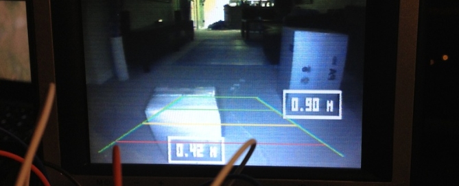
Now that we can get the sensor data to the second Arduino that has control of the Video Experimenter shield, we can start displaying the data. First things first, however. The camera I have picked already draws some sort of alignment lines to help with parking. The trick is to overlay the sensor information in such a way as to “highlight” the objects on camera where they actually are. For this, I’ve set up a test rig. Another important thing is we want to align the data in such a way as to give the user the perception of “tracking” an object. So, looking through the camera as you’re getting closer to something, […]
  • Parkonator – Part 2 Parkonator – Part 2

    Parkonator – Part 2

Parkonator – Part 2

Parkonator

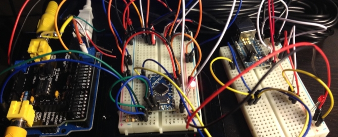
In Part 1 of the blog series I described how you can use an Arduino to capture and decode parking sensor data from cheapo parking sensors found all over Amazon. In this part I will talk about how to send this data over from one Arduino to another using I2C protocol and why you even need to worry about that.

Video Experimenter Shield

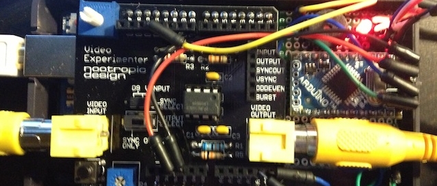
First, a word about the Nootropic Video Experimenter shield. This shield is pretty sweet, it’s cheap, it uses the TVOut library and it works pretty much as advertised. The shipping is quick too! We’ll use this shield to overlay the parking sensor information over the composite video signal coming off the read view camera (this will be described in part 3). So, […]

  • Advanced box detection!
    Parkonator – Part 1 Parkonator – Part 1

    Parkonator – Part 1

Parkonator – Part 1

“Parkonator”

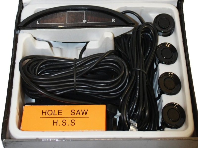
Historically I have preferred car stereos that look like they actually came with the car. My particular head unit is a Clarion CX609, I like it because it matches the green interior lights of my car (as much as I dislike green as an interior color). However, recently I’ve been keeping an eye out for an Android powered double din head unit. In particular, the Parrot Asteroid Smart, which just looks cool as hell for a variety of reasons. My car (2005 Pontiac GTO) is notoriously hard to see out of, especially when parking. I figured I could use the new stereo’s ability to display video from a reverse camera, and perhaps I could even spice it up a bit.. A few weeks ago I’ve picked up a pair of cheap generic SE4 parking sensors from Amazon. I believe these are very similar to the better known Pyle brand sensors. Using an Arduino, I was able to hack these to overlay parking sensor information on top of a cheap license plate mounted reverse camera. With these tools, the Parkonator project was born!

Components

This project required a few things to work:No, the box wasn't actually this fancy.

Hacking The Parking Sensors

First things first, I had to somehow extract the sensor information from the parking sensor system. Each box arrived with 4 sensors, a controller and a little display that […]