This is the final part of the 3-part series about the Parkonator, a device that overlays parking sensor information on top of any RCA backup camera.
Video Overlay
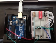
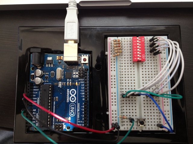
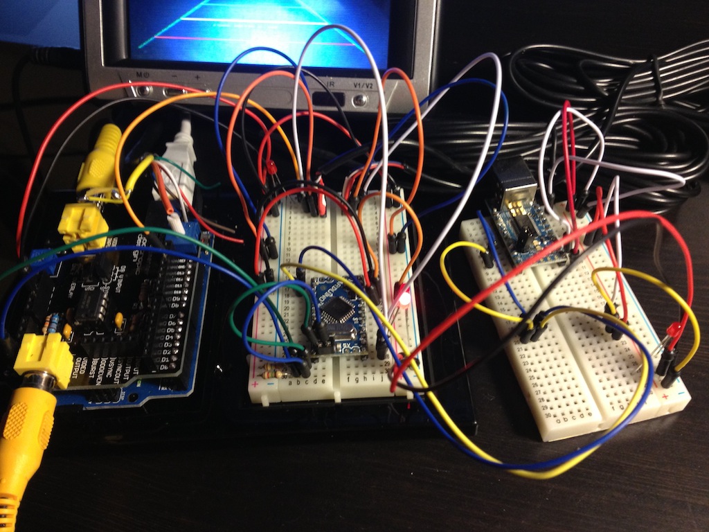
 Now that we can get the sensor data to the second Arduino that has control of the Video Experimenter shield, we can start displaying the data. First things first, however. The camera I have picked already draws some sort of alignment lines to help with parking. The trick is to overlay the sensor information in such a way as to “highlight” the objects on camera where they actually are. For this, I’ve set up a test rig.
Basically, I pinned the parking sensors (mounted in fancy cardboard) to a wall as if they were mounted in my car’s bumper. I have some advice about that: mine are hanging too low. I didn’t realize this until I mounted them in the car. The problem is, the sensors use ultrasound to detect the distance to an object. Evidently, carpet isn’t all that great at reflecting sound waves, so I never noticed any issues during my testing. However, concrete and other paved surfaces will cause your sensors to get a lot of false signals from the sound waves bouncing off harder surfaces. Mine are mounted fairly low in my car, as a result I’ve noticed some noise every now and then (as you can see in the videos below).
Another important thing is we want to align the data in such a way as to give the user the perception of “tracking” an object. So, looking through the camera as you’re getting closer to something, objects that are far should move slower on the screen than objects which are close. It’s hard to put into words, but check out this graph that shows the Y-coordinate (in pixels) on the screen compared to the distance at which the object is standing from the camera (in cm).
![]()
On the Y axis is the screen pixel. On the X axis is the distance an object would have to be standing away from the camera to show at that pixel. Notice it’s non-linear. My first gut instinct was to approximate this thing with a polynomial. However, I later opted for a simple table and an interpolation algorithm because even on paper you could see that it would be much faster to interpolate. In code it looks something like this:
// Pixel and distance information related to guide lines drawn by camera.
// Super-far, kinda-far, 1st green line, 2nd green line, yellow line, red line, bottom
#define MARKERS 7
int pixel[MARKERS] = {32,37,44,51,55,63,H-1};
int distance[MARKERS] = {253,253,253,190,150,110,80};
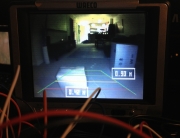
This allowed me to accurately match the sensor information with the objects on camera. Check out this test with boxes!
Next there was the issue of expiring old values. When the sensors don’t detect anything, they just don’t send any signal. So your image appears “frozen” after the object goes out of range. As a result, there needs to be an algorithm that expires old values if they haven’t been updated for some time.
To complicate things, the sensors send updates with different intervals at different distances. For example, if the object is really far, you might get an update every 4-5 seconds. If the object is within a meter or so, the updates are much more frequent, close to 3 times a second or about every 350 milliseconds. When the object gets really close, the updates slow down again to about once a second. The graph below shows the approximate update interval in relation to distance:

The sensors don’t really have a range much beyond 190 cm (about 2 meters). But that’s still plenty. In code, it looks something like this (snippet):
// Sensor value ranges
#define MAX_DIST 191
#define MIN_DIST 23

// How long until the sensor value is set to out of range.
#define TTL_CLOSE 750
#define TTL_MED 350
#define TTL_FAR 150
#define TTL_REALLY_FAR 1500

#define VALUE_CLOSE 50
#define VALUE_MED 90
#define VALUE_FAR 140

volatile byte values[2][4];
volatile boolean valueChanged[2][4];
volatile unsigned long timestamps[2][4];
unsigned int group;
unsigned int id;
unsigned long lastExpired;

// If not heard from sensor in TTL ms, set value as out of range.
boolean expireOldValues() {
boolean expired = false;
if (millis() - lastExpired < TTL_FAR) {
return expired;
}
lastExpired = millis();
for (group = 0; group < 2; group++) {
for (id = 0; id < 4; id++) {
long ttl = TTL_REALLY_FAR;
if (values[group][id] <= VALUE_CLOSE) {
ttl = TTL_CLOSE;
} else if (values[group][id] >= VALUE_CLOSE && values[group][id] <= VALUE_MED) {
ttl = TTL_MED;
} else if (values[group][id] >= VALUE_MED && values[group][id] <= VALUE_FAR) {
ttl = TTL_FAR;
}
if (millis() - timestamps[group][id] > ttl && values[group][id] != OUT_OF_RANGE) {
values[group][id] = OUT_OF_RANGE;
valueChanged[group][id] = true;
beep();
expired = true;
}
}
}
return expired;
}
So that’s that. I’ll attach the Arduino sketch at the bottom of this page. Next, let’s move on to installing the thing into the car.
Car Install and Calibration
 As I mentioned earlier, I mounted my sensors far too low, because I wanted them to be in the black plastic part of my bumper and not the yellow area. As a result, I do pick up occasional noise. That’s something I’m going to try and filter out at a later time.
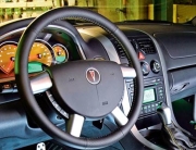
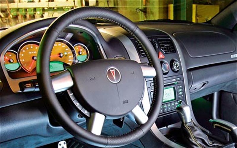
Anyway, if you’re using an aftermarket backup camera like I was, you’ll want to align the camera’s guide lines with the real world so you can have a somewhat accurate representation of your car’s dimensions. It honestly would have been better if I could just draw my own, but whatever. Best way to do this alignment is with laser guides as you see in the picture on the right.
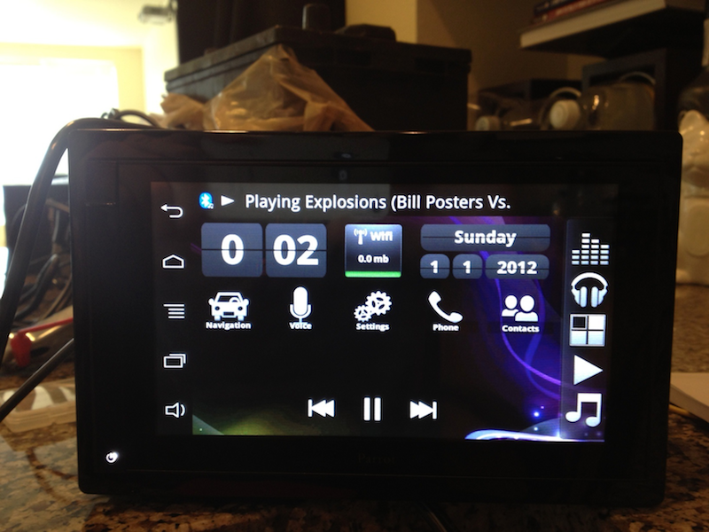
Once aligned, you need a large object, like a box, to move around and re-calibrate the distance to pixel tables. If your camera draws lines for you, this shouldn’t take long as you just need to place the large object on a line and enter the value you get from the sensors. Easy enough. With that done, I added some additional display elements (like a bar graph) to aid in parking really close to things (where you can’t see much except a wall through a camera). The results? See for yourself:
Wall Test
Car Test
You can see the sensor noise really manifest itself in this one. It doesn’t usually happen this bad.
Source Code
The complete source code can be had here:
Arduino Mini (for sensor data gathering)
Arduino Uno (for overlaying the data)
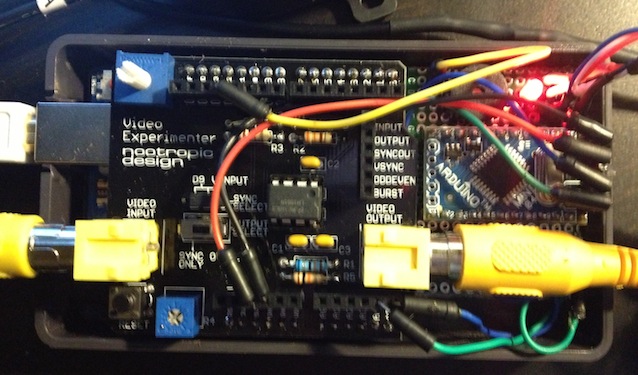
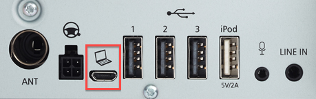
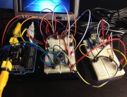
Hope you found this somewhat interesting and maybe even useful. Personally, this is one of the most useful things I’ve built in a long time. I’ve been driving with it for about 2 weeks now and I have to say, backing into parking spots is my favorite part of the drive now 😀 If you have any questions related to the code, I’d be happy to clear those up! PS: here’s the final layout of all the connections:


You should sell these, Alpine markets them for $300+.
Heh, thanks! I looked into it, but in the end I think it’s better to just leave the whole thing open sourced so others can build and tinker with their own
Yuri,
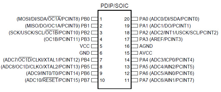
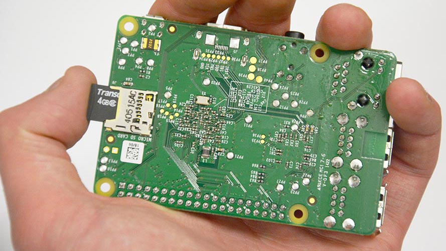
In the interest of saving some money (and being able to keep my arduino boards) I developed a shield compatible circuit that you can plop two AVR’s, two crystals, four caps, and two resistors to. I etched the board via a photo resist method, and the video experimenter shield SHOULD just plug right into the female headers.
I didnt have any room to label the parts but you should be able to trace them out to see what they are. This version should save a bit of money too. The only thing you may need to modify is some of the code because D10 is used in both the uno and the mini on your project. I didn’t need the sensor pin because I am only using reverse, and it is auto activated by the power coming from the sensor switch.
Take a look:
http://imgur.com/Wy3mJ3m
http://imgur.com/4RJhhNV
Feel free to look, but please don’t sell for monetary value 🙂
This is very cool, thanks for sharing, Jamie! I have no plans to sell this thing, hence why it’s open source 😉 I have been considering doing something like that, but you know, “if it works – don’t fix it” haha. So for now I’m just running my two boards. But this is very cool! Do you have a functional circuit up and running? Would be cool to see another setup working. Let me know, I’d be more than happy to link to your project page if you get around to making one.
the more efficient way to imnlemept the same sketch could have been using the mod function instead of repeating the same if again and again.Nice resource still! Thanks
I love technology. I love it.Despite that, I wish my car had less. I would prfeer saving a few thousand on a disposable necessary item. I want a comfortable seat, a mediocre stereo that I can pull out and change if desired, cruise control, automatic headlights, good fuel economy, and iron free panels where rust normally occurs first. If it could run on electricity, that would be awesome. Then offer it in the form I want it. During high school, four doors and a back seat was nice. In college, I just wanted a two door hatchback. And now that I have a family I am driving something bigger. But, the criteria I listed is what I have constantly valued. And for God’s sake, it is a marginal cost difference to build something that looks like a mustang versus building something that looks like an escort
I actually just soldered it up:
http://i.imgur.com/WV5NUxL.jpg
http://i.imgur.com/B62CDYB.jpg?1
It stacks with the shield on it wonderfully. Now all you need is the power/ground/TX wires from the little switch plugged into their appropriate holes on the shield and it powers the underlying board for you.
Very pleased with it so far.
That’s really cool! Great piece of work! Now just make sure you don’t mount the sensors too low like I did, so you don’t get any noise 😉 I’m working on a noise filtering algorithm in my free time.
Great project. I’m working on building something very similar. I’m still struggling with the parking sensor decode at the moment. I also have a some impedance issues with the control box which doesnt work without the display attached! Took a while to figure that out! Although all these boxes look the same(mine looks exactly like yours) the serial protocols all seem to be different. I think mine is 4 frames of 13 bits but I’m still not 100% sure of it. I’m pretty sure it’s PWM (they all seem to use PWM) I’ve approached it by disconnecting all sensors then tracing. Adding one sensor then tracing etc. Problem is when I repeat it I seem to get different frame patterns every time! There isn’t an obvious multi-frame sync pulse or preamble.
I am starting to wonder if mine is an “analog” protocol where the pulse position/sequence is counted by the display to derive the distance rather than being sent a digital value for the distance by the controller.
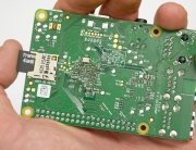
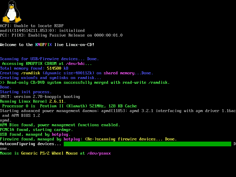
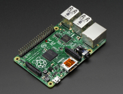
I’ve been looking at the MAXIM OSD shield for the video overlay. This shield has a screen buffer so no timing issues for the display. I havent seen thee video experimenter shield before – need to examine in more detail. This one might be a good option to use with the Raspberry Pi instead of the Arduino.
In my case, there’s a very long 30ms pulse before a number of fast 8-17us pulses which are the actual data. Does yours have a long pulse before the bytes are sent? It’s possible that instead of sending the data for all four sensors at once, it just sends the data for the particular sensors which are connected. In my example, the data contains the sensor ID and the value. The Track Roamer project I referenced has a different pattern. You’re correct in assuming they’re all different.
I picked the Video Experimenter shield for its compatibility with the TVOut library. It allows for simple vector graphics (squares, circles, etc). I believe Maxim OSD is strictly for character overlay.
I spent some time looking at it last night. I don’t have a scope or logic analyser so I’m using the Arduino to collect the signal data so the resolution is not perfect. It’s a PWM scheme for binary representation of sync and I suspect either PPM or PDM based for the data. The long pulse is around 20.7ms, a shorter pulse of 1.3ms and short pulses of 120us. After last night I discovered these short pulses vary in length between 120uS and about 680us.
With no sensors attached I can get a predictable sequence S=short
SS-101-SS-101-SS-101-SS- pattern repeats
With all sensors attached and 0m on the distance for all sensors I get
SSS-1-SSS-1-SSS-SSS-101-SSS-1-SSS-1-SSS-1-SSS-101
The 101 seems to be a framing signal. It is the last sequence where I discovered that the duration of the S pulses varied leading me to think that each block of 4 is some kind of PDM or PPM modulation scheme representing the data for each of the 4 sensors but the data for non sensors connected contradicts this.
I’ve ended up ordering another parking sensor box from eBay to see if I fair any better with a different one otherwise I’ll mod the control board and tap into the signals from the analog multiplex and do my own pulse echo detection!
The Maxim OSD is a character overlay. It is possible to do user defined characters and hence basic graphics.
The blog interpreted part of my post as HTML and deleted it! It should have read:
With no sensors attached I can get a predictable sequence S=short
SS-101-SS-101-SS-101-SS- followed by 35 bits of alternating 10 then the pattern repeats
The new parking sensor arrived. Although the board is a different design it uses the same protocol. It looks like there is a company in China providing the Haier micro-controllers for these pre-programmed. So I got hold of a Saleae logic analyser and captured the protocol. After lots of being puzzled I figured it out. It’s a PWM scheme but it’s the 0 volt not the +5V volt that indicates the mark state. The +5V pulse durations are all over the place in length but the 0V durations are pretty predictable. The parking sensor protocol has lots of deadtime and lots of framing pulses with no data. Each frame is 21m long and marked by +5V. There are empty frames in a 7,2,2,5 pattern – not sure why. The data frame starts with a 0V pulse of 138us followed by a +5V pulse of 30us and 78us 0V pulse and then a =5V pulse of 34us. The data burst now starts. A 0V duration of 34us is a logic 0 and a 56us duration is a logic 1. The frame is 4 bits (nibble) which is the sensor address followed by a nibble of 1,1,1,1. Then there is a byte of data from the sensor. This is then followed by +5V for 328us and a 0V for 276uS to indicate the end of the data burst. The distance byte is from the object so reads 00H for 0m and a max of 63H when no sensors connected. I still need to figure out the reason why both of these devices won’t work without the display attached. The inhibit line on the analog mutiplexer is set if the display isn’t attached so somehow the data line must sense it is attached. Needs more investigation. To use with the arduino I’ll need to come up with a buffer circuit for the digital pin since it seems to have too a low impedance on the data line and drags it down.
Interesting. Looks like the communication protocol for these boards is all over the place. Glad you’re getting it figured out!