I’ve been needing to use an AVR controller with a lot of GPIO to receive commands over Serial and control two servos (along with a few other devices). One thing I noticed after building the PCB is that there aren’t a whole lot of libraries available for servo control for the x61 series because this chip has a really weird 10-bit timer, while most other chips have either an 8-bit or 16-bit timer.
8-bit timers aren’t great for servo control because their resolution limits your range of motion. If you want to rotate the servo from 0 to 180 degrees, you may be limited to rotating 2-3 degrees at a time, instead of the 1 degree increments. For some this may be fine, but for my application I wanted to maximize the resolution. Another problem with 8-bit libraries is that they typically use Timer1 interrupts to pulse servos. If your chip isn’t doing much more than just running the servos, that’s not a big deal. But if you plan on using Serial, and do other things – you’re going to quickly notice that Timer1 interrupts interfere with the chip’s operation. For example, on the x61 the Serial is implemented in software and uses pin change interrupts, which themselves can get interrupted by your servo timer. You end up with working servos, but unusable Serial comms.
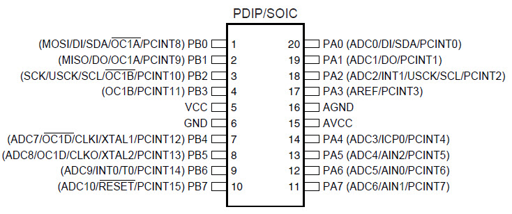
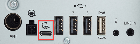
So with that in mind, I’ve set out to figure out how to use hardware PWM to drive two servos without using Timer1 interrupts. You’ll notice that the chip has 3 PWM pins (OC0A, OC1B, OC1D). The pins we’ll be using here are OC1B (PB3) and OC1D (PB5). These pins are directly connected to the servo’s signal wires.
Prerequisites
- I’m using the Arduino IDE for this project.
- ATTinyCore – this will allow you to compile and load code onto the AVR chip.
- I’m using the internal 1 MHz oscillator because it works best with the soft Serial implementation.
- You will need an AVR programmer, like this one.
I will not be covering how to connect the programmer to the chip, or how to set up the Arduino IDE and ATTinyCore. You should be able to get going from the provided documentation.
Side Note
If you don’t care about driving the servos via hardware PWM and want to use an internal 8MHz clock speed, I have created an interrupt-driven servo library for the x61 series which you can get from my Git repo. I have been talking to creators of ATTinyCore to include it as the default library, but for now it lives separately. And honestly, it could use a bit of work to get quite right.
Hardware PWM
So how do we generate PWM pulses with 10-bit resolution and without using interrupts? Well, this took a lot of research and a week of digging through the data sheet and experimenting.
The trick is to set the chip to 10-bit PWM6 mode and use the OCR1B and OCR1D compare registers to control the pulse width. Here’s some info about PWM6 mode from the data sheet:
The PWM6 Mode (PWM1A = 1, WGM11:10 = 1X) provide PWM waveform generation option e.g. for controlling Brushless DC (BLDC) motors.
Here is the code necessary to set up hardware PWM to output separate signals on pins PB3 and PB5. Please pardon my code highlighter plugin, it doesn’t seem to handle spaces well.
// Servo angle defines.
#define ANGLE_MIN 0
#define ANGLE_MAX 180
#define PW_MIN 70
#define PW_MAX 330

/**
* Atomically write pulse width to pin 4.
* @param i OCR1D compare steps.
*/
void writePulsePin4(unsigned int i) {
   unsigned char sreg = SREG;
   cli();
   TC1H = (i >> 8);
   OCR1D = (unsigned char)i;
   SREG = sreg;
}

/**
* Atomically write pulse width to pin 6.
* @param i OCR1B compare steps.
*/
void writePulsePin6(unsigned int i) {
   unsigned char sreg = SREG;
   cli();
   TC1H = (i >> 8);
   OCR1B = (unsigned char)i;
   SREG = sreg;
}

void setup() {
   // Save interrupt flag register
   unsigned char sreg = SREG;

   // Disable interrupts
   cli();

   // Set TOP value to 10-bit resolution
   TC1H = 3;
   OCR1C = 0xFF;

   // Set servo pulse width to match 90 degree rotation.
   int defaultPw = PW_MIN + (PW_MAX - PW_MIN) / 2;
   writePulsePin4(defaultPw);
   writePulsePin6(defaultPw);

   TCCR1B = _BV(PWM1X); // Invert PWM
   TCCR1B |= _BV(CS11) | _BV(CS10); // Set prescaler PCK/4

   // PWM6 Mode
   TCCR1D = _BV(WGM11) | _BV(WGM10);

   // This goes into "attach servo" code.
   TCCR1A = _BV(PWM1B); // Enable PWM on OC1B (pin 6)
   TCCR1C = _BV(PWM1D); // Enable PWM on OC1D (pin 4)

   TCCR1A |= _BV(COM1B1) | _BV(COM1B0); // Enable PWM on pin 4
   TCCR1C |= _BV(COM1D1) | _BV(COM1D0); // Enable PWM on pin 6

   // Select pins 4(OC1OE3) & 6(OC1OE5) for PWM
   TCCR1E = _BV(OC1OE3) | _BV(OC1OE5);

   // Restore interrupt flags
   SREG = sreg;
}

void loop() {
   // Rotate both servos from 0 to 180 degrees.
   for (int i = ANGLE_MIN; i <= ANGLE_MAX; i++) {
      unsigned int pw = rotationToPw(i);
      writePulsePin6(pw);
      writePulsePin4(pw);
      delay(100);
   }
   // Rotate both servos from 180 to 0 degrees.
   for (int i = ANGLE_MAX; i >= ANGLE_MIN; i--) {
      unsigned int pw = rotationToPw(i);
      writePulsePin6(pw);
      writePulsePin4(pw);
      delay(100);
   }
}

/**
* Converts a rotation (degrees 0 to 180) to number of timer steps.
*/
unsigned int rotationToPw(byte rotation) {
   return (unsigned int)(((float)rotation / (float)ANGLE_MAX) * (PW_MAX - PW_MIN) + PW_MIN);
}
Questions? Feel free to ask in the comments and I’ll try to explain to the best of my ability.


Great post